Pilot-scale systems

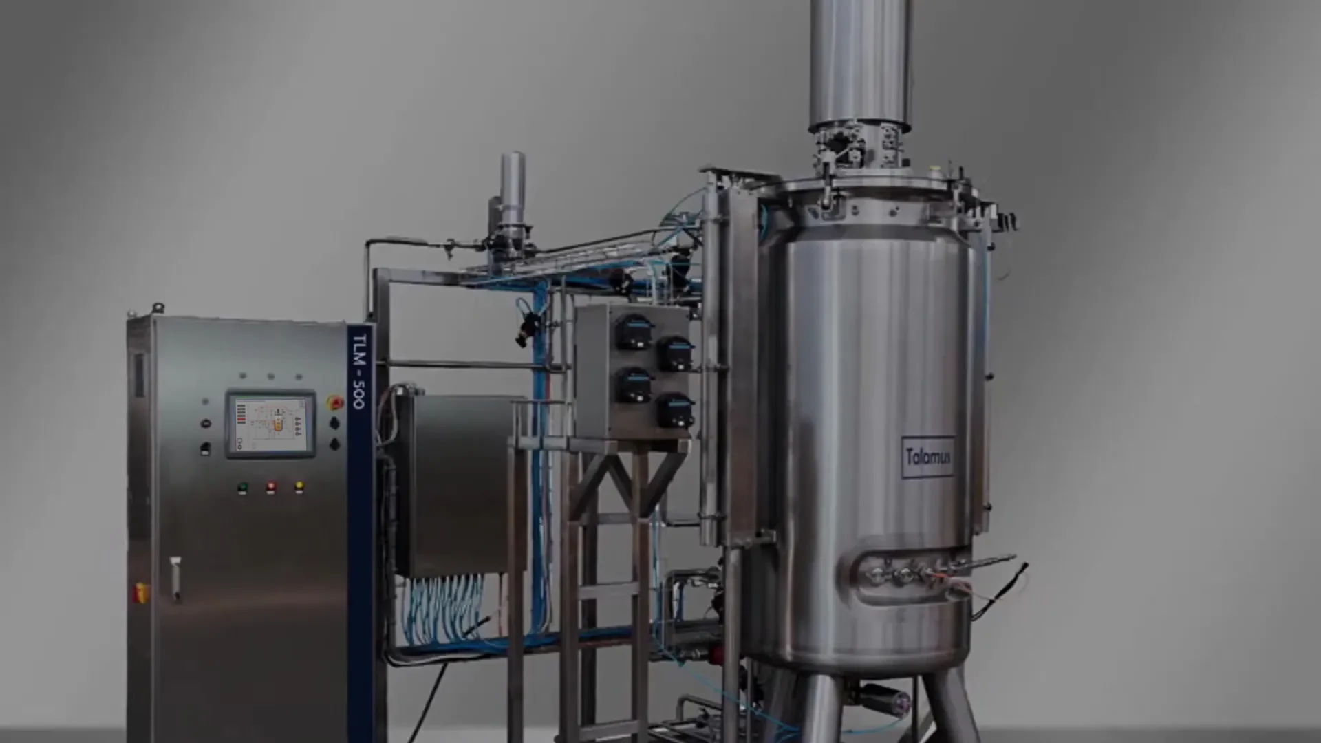
TLM500 pilot bioreactor

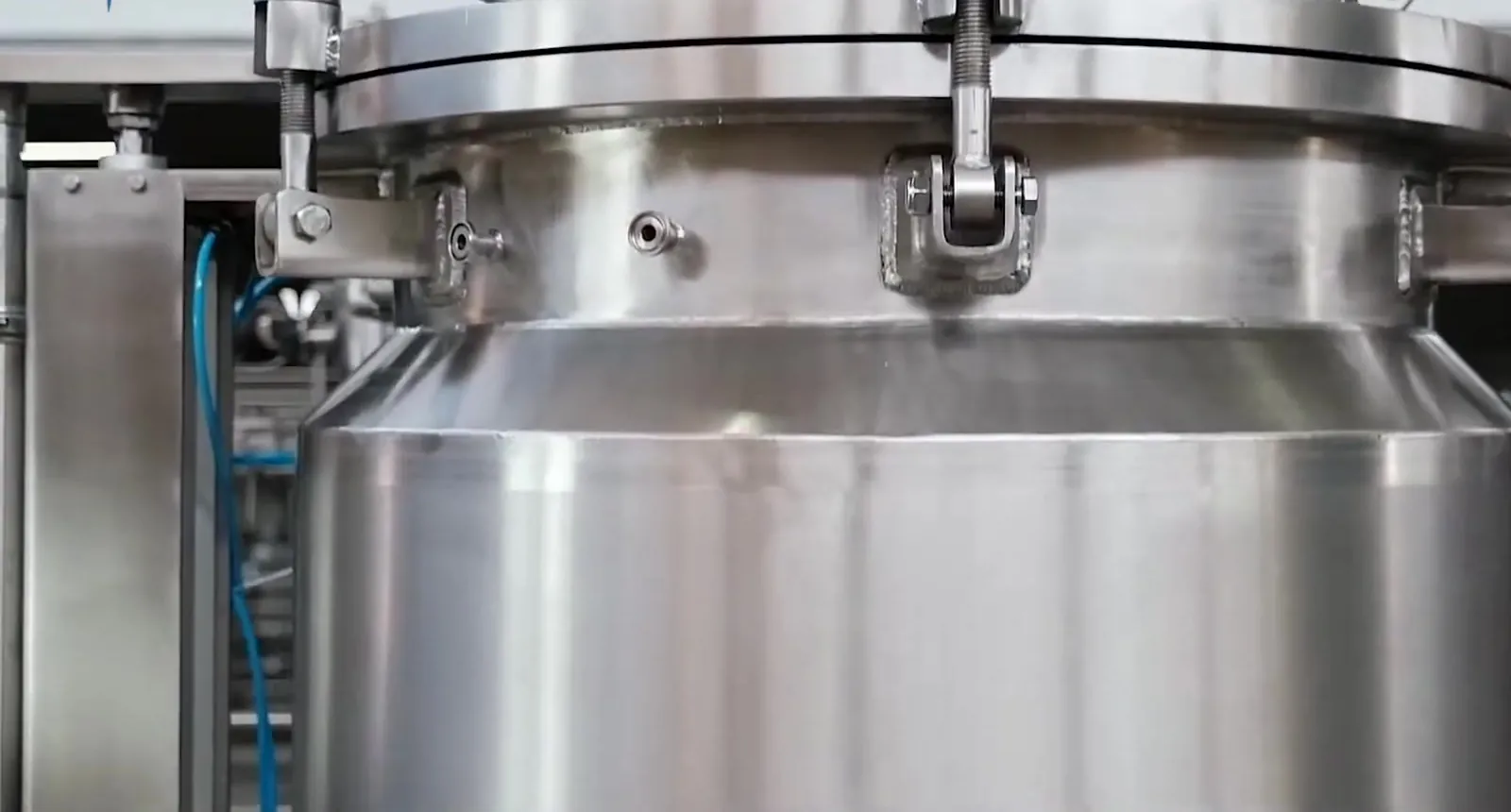
Pilot scale is the scale-up step before commercial production. Talamus pilot systems run the sterilisation in place (SIP), controlled cooling and cultivation phases automatically. The system integrates with plant utilities (steam, cooling water, compressed air).

Request a technical consultationFor food, agricultural and industrial biotechnology producers running scale-up, pilot production and pre-commercial batches.

TLM120

20 L seed reactor + 100 L pilot reactor

TLM120 is a pilot system with automated phase management, consisting of a seed reactor and a pilot reactor. We deliver both vessels on a shared skid together with valves, instrumentation and the control unit.

  • Sterile transfer from the seed reactor to the pilot reactor
  • Automated sterilisation in place (SIP) and phase control
  • Time-stamped logging of the defined process variables for scale-up studies
TLM500

500 L working volume (600 L total)

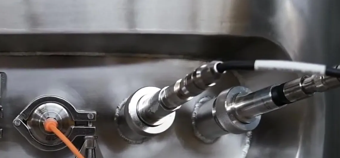
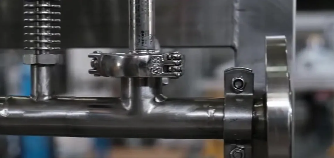
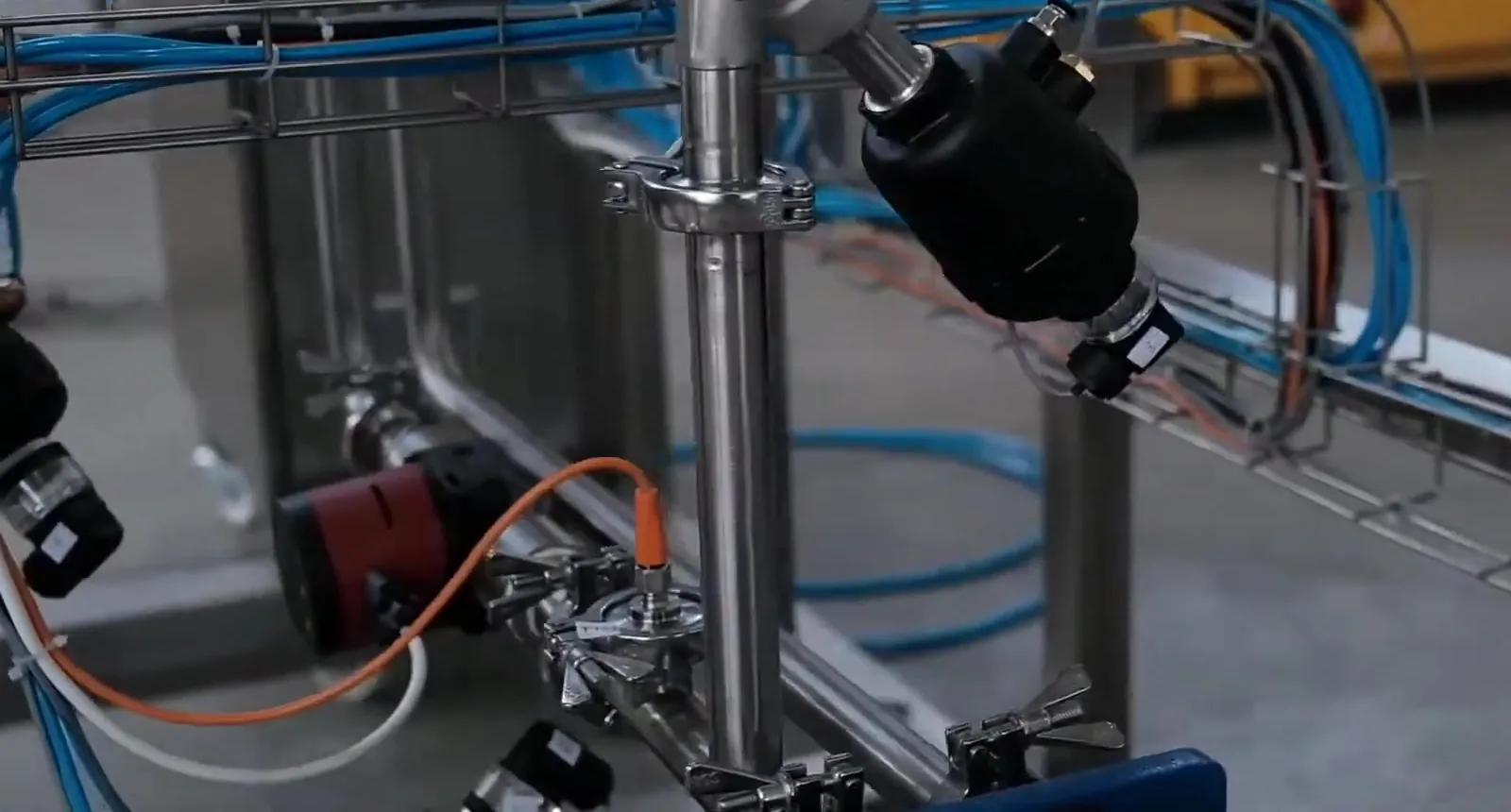
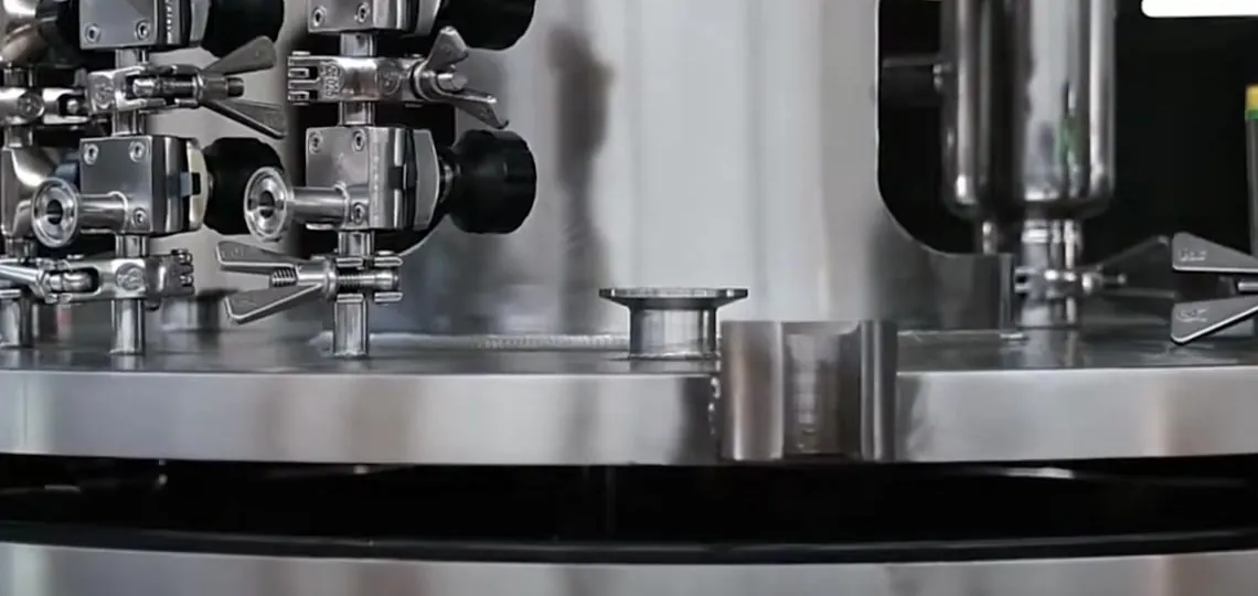
The TLM500 photographs on this site show this system.

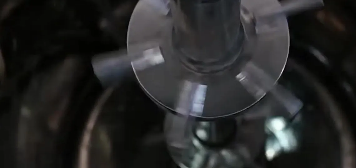
TLM500 is a jacketed, stirred pilot and pre-production reactor. It operates with plant steam, cooling water and compressed air connections. SIP, controlled cooling and cultivation phases run automatically. Harvest follows steps defined on the control unit.

TLM500 technical data
Volume and materials
Working / total volume500 L / 600 L
Product-contact surfacesAISI 316L, certified material
ConnectionsHygienic connections; drainage slope and permissible dead-leg L/D ratios defined in the project P&ID and fabrication documentation
Surface roughnessTarget Ra of product-contact surfaces, weld finishing and passivation scope stated in the project documentation
Mechanical
Heat transferHeating and cooling through the jacket; jacket type and heat transfer area in project documentation
AgitatorTop-driven; impeller type and number of stages selected for the process
LidLifting device for maintenance access
Pressure and temperature ratingIn project documentation
Sterilisation, gas and liquid
SIPAutomated; vessel and filter lines. Hold time and acceptance criteria in project documentation
CIPCIP equipment; cleaning cycle, chemical dosing and validation scope defined per project
AerationMass-flow controlled, sterile-filtered
DosingAcid, base, antifoam, feed
Sampling and harvestSterile sampling port, harvest valve
Measurement and control
ControlClosed-loop control for temperature and pH; configurable cascade control for DO; threshold-based dosing for foam
Monitoring and interlocksLevel and pressure monitoring; interlock conditions in project documentation
Standard sensorsAnalogue or digitally communicating pH measurement chain depending on model, optical DO, temperature, hydrostatic level, pressure, air flow
PAT optionsIn-line biomass/OD, viscosity, exhaust gas, dissolved CO₂
Controller and interfaceIndustrial PLC, PID loops, touch-screen operator panel (HMI)
Field communication4–20 mA analogue signal or digital communication such as Modbus, depending on the sensor/transmitter model
Delivery
ScopeSkid-mounted; piping, valves, instrumentation, control unit
Site utilitiesSteam, oil-free compressed air, cooling water, water of the quality required for process and cleaning, power

* Given in project documentation: pressure and temperature rating, motor power, surface roughness and supplier model codes.

TLM500 components

Automated SIP, cooling and cultivation phases

The operator selects the process phase; the related valve positions, permissives and control loops engage in a defined sequence.

TtSchematic view; set points are defined in the project documentation.

Plant steam is used for jacket heating, while the product-contact sterilisation in place (SIP) circuit uses steam of a quality suited to the process requirement. Steam distribution, condensate drainage, temperature measurement points, hold time and any required isolation or protection arrangements are defined within the project. SIP conditions are managed within equipment and sensor limits.

  • SIP including the vessel and the inlet and exhaust gas filter lines
  • Automated SIP cycle started from the control unit
  • Sterility maintained on sampling and feed lines

TLM120 and TLM500 construction

Product-contact surfaces

  • Stainless steel with material certificates (AISI 316L)
  • Target surface roughness (Ra), weld finishing and passivation scope are stated in the project documentation
  • Hygienic connections designed for drainability and cleanability; permissible dead-leg lengths and L/D criteria are defined in the project documentation
  • Design pressure, test method and acceptance criteria for vessel and jacket are documented to the applicable project standard

Heat transfer, gas and valves

  • Heating and cooling through the jacket; jacket type and heat transfer area stated in the project documentation
  • Mass-flow-controlled, sterile-filtered gas line
  • Pneumatically actuated process valves with position feedback
  • Piping, valves, instrumentation and control unit on a shared skid

Process instrumentation

  • Analogue or digitally communicating pH measurement chain depending on the selected model, and optical dissolved oxygen sensor
  • Hydrostatic level and vessel pressure measurement
  • 4–20 mA analogue signal or digital communication such as Modbus, depending on the sensor/transmitter model
  • We select instrumentation with calibration, technical service and spare-part availability in mind
  • Process analytical technology (PAT) options: in-line biomass/optical density, viscosity, exhaust gas analysis and dissolved CO₂

Sterilisation and cleaning

  • Automated steam sterilisation in place (SIP) including filter lines; scope defined in the project documentation
  • Cleaning in place (CIP) equipment; chemicals, temperature, flow, duration and return design set per project scope
  • Maintenance access with a lid lifting device
  • Sterile sampling and feed ports

Site conditions defined before installation

We review the plant utility values in the first meeting and define them in the project documentation.

  • Plant steam: availability, pressure and quality
  • Compressed air: flow, pressure and oil-free/dry conditions
  • Cooling water or chiller capacity
  • Water quality, flow and pressure required for process and cleaning
  • Electrical infrastructure and panel location
  • Layout: skid, control unit and service clearances

Technical consultation request

Information on the target batch volume, seed stage and the steam, air and cooling utilities available on site is sufficient for an initial assessment.